The end of the 2D drawing era
Relying on 2D drawings to communicate product requirements is no longer sustainable. Modern products move too fast, supply chains are too distributed, and the cost of misinterpretation is too high.
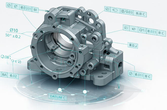
That’s why manufacturers are shifting to Model-Based Definition (MBD), a model-centric approach where GD&T, materials, tolerances, surface finishes, and manufacturing notes live directly in the 3D CAD model.
The model becomes the authority. Not the drawing. Not the PDF. The model. When done right, MBD becomes the backbone of a true digital thread, from design through manufacturing, inspection, and supplier collaboration.
A true single source of truth
MBD eliminates the disconnect between 3D geometry and 2D documentation. All Product Manufacturing Information (PMI) is embedded directly in the model, meaning:
- No duplicated data.
- No drawing/model mismatches.
- No “which version is correct?” conversations.
Using Siemens NX, engineers can author semantic PMI that downstream systems actually understand, not just annotations that look right on screen. With Teamcenter, that authoritative model is version-controlled, traceable, and securely shared across the enterprise and supply chain.
Faster, cleaner downstream handoffs
When PMI is embedded correctly, downstream systems don’t need translation:
- CAM tools can consume tolerances directly.
- CMM software can auto-generate inspection paths.
- Manufacturing engineering can plan with confidence.
This eliminates weeks of manual interpretation and setup time, especially for complex, tolerance-sensitive parts.
Automated change propagation
This is where MBD really pays off. In a model-based workflow:
- A design change updates the model.
- PMI updates with it.
- Manufacturing and inspection data stay aligned.
With Teamcenter change management, those updates are tracked, approved, and visible to every stakeholder. No silent changes. No outdated files floating around email inboxes.
Reducing documentation errors with embedded PMI
Most manufacturing errors don’t come from bad design, they come from bad communication.
Why embedded GD&T matters
3D GD&T attached directly to features removes ambiguity:
- Machinists see exactly what feature the tolerance applies to.
- Inspectors see the same intent as engineering.
- No guessing based on flattened views.
Traditional 2D drawings simply can’t provide this level of contextual clarity.
Eliminating version chaos
PDF drawings are notorious for:
- Being downloaded once and reused forever.
- Getting shared outside formal change processes.
- Becoming outdated the moment a revision happens.
By managing MBD models in Teamcenter or Teamcenter X, teams always reference the current, released version, whether they’re internal users or external suppliers.
The real cost of poor MBD execution
MBD is powerful, but sloppy implementation creates new risks. Common failure points include:
- Incomplete PMI forcing downstream teams to “fill in the blanks”.
- CAD, CAM, and inspection tools that can’t consume semantic PMI.
- Weak PLM integration that allows duplicate or offline models.
- Suppliers stuck in 2D-only workflows.
- Cultural resistance from teams used to prints.
This is why MBD is not just a CAD initiative, it’s an enterprise change.
MBx implementation stages (reality, not theory)
Model-Based Drawings (MBDw). A hybrid phase where:
- 3D models contain PMI.
- 2D drawings are auto-generated for comfort and transition.
This stage builds trust without forcing immediate change.
Model-Based Definition (MBD)
- The 3D model becomes the contractual authority.
- No standalone drawings.
- PMI is complete, semantic, and consumable downstream.
Model-Based Enterprise (MBE)
- Design, manufacturing, inspection, quality, and suppliers all work from the same model.
- Full digital thread.
- High automation, high traceability, lower cost of change.
Every company progresses differently, but skipping steps usually backfires.
Best practices for a successful MBD rollout
Crawl: Pilot with intent
Start with:
- Low-risk, high-learning parts.
- Clear success metrics.
- Tight feedback loops.
Walk: Train and standardize
- Train engineers, manufacturing, and QA on reading and authoring 3D PMI.
- Align on standards like ASME Y14.41, STEP AP242, and QIF.
- Bring suppliers into the conversation early.
Run: Integrate and scale
- Validate NX PMI flows cleanly into CAM, CMM, and inspection tools.
- Use Teamcenter to enforce version control and change governance.
- Scale across programs once the process is stable.
Why Siemens NX + Teamcenter are built for MBD at scale
Many tools can create 3D models. Fewer can support enterprise-grade MBD.
Siemens NX
- Native authoring of semantic PMI and GD&T.
- Proven support for STEP AP242 and QIF workflows.
- Tight integration with CAM and simulation.
Teamcenter / Teamcenter X
- Manages MBD as a governed, traceable asset, not just a file.
- Controls revisions, changes, and access across teams and suppliers.
- Teamcenter X adds SaaS flexibility: no servers, no upgrades, faster rollout.
Together, they support MBD not as a point solution, but as a system of record for product definition.
The Bottom Line
Model-Based Definition isn’t about eliminating drawings for the sake of it.
It’s about eliminating confusion, rework, and wasted time. Manufacturers that get MBD right:
- Release products faster.
- Make fewer mistakes.
- Scale collaboration without scaling chaos.
And those that pair MBD with Siemens NX and Teamcenter put themselves on a clear path toward a true Model-Based Enterprise. Want to learn how we can help you with MBD?